
Injection moulding is a very common manufacturing technology for the mass-production of plastic parts. If you look at the plastic parts around you, it is more likely than not, that they will be injection moulded.
Tooling for injection moulding can be expensive, depending upon the complexity of the mould. A mould can cost from $3,000 to $100,000 or more depending on the size and complexity of the part. However, after the initial tooling investment the parts are; low cost, highly repeatable, and with good tolerances. Because of the initial cost of tooling, it is often not a cost-effective solution for low volumes.
To achieve the full benefits of this manufacturing process; certain design guidelines should be followed. This article will explain best practice for injection moulding, however as a design engineer myself I know it is not always possible to follow all these guidelines exactly. When this scenario occurs, there is always a solution, however it often means a slightly more expensive tool and/or part cost. This is often a compromise we must strike as engineers to find the best all-round product solution.
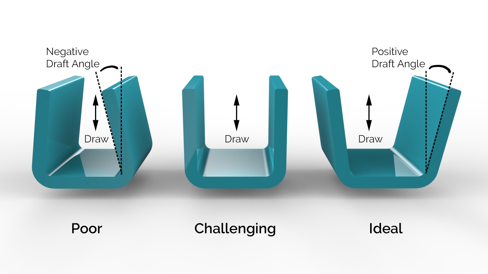
Add a Draft to Vertical Walls
To allow the part to eject from the mould easily a draft angle must be added to all vertical walls. This reduces wear on the tool and reduces the possibility of drag marks on the surface of the part.
- A good rule of thumb is 1 degree of draft for every 25mm of cavity depth.
- Ideally with a minimum of 2 degrees.
- Also, the draft may need to be increased if you want a more textured surface finish.
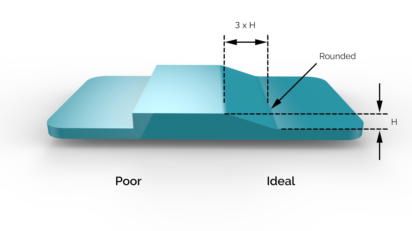
Uniform Wall Thickness
A uniform wall thickness ensures consistent cosmetic and strength of parts. Too thick and you may have unsightly sink marks, warp or internal voids. Too thin and the molten plastic may harden before filling the mould (i.e. voids in the part). If different thicknesses are required, then make the transition as smooth as possible. All of this ensures the material can flow as easily and consistently within the mould.
The following are recommended wall thickness for different materials:
| Material | Recommended Wall Thickness (mm) |
|---|---|
| General Rule of Thumb | 1.2 – 3.0 |
| ABS | 1.1 – 3.5 |
| Acetal (POM) | 0.6 – 3.8 |
| Liquid Crystal Polymer | 0.75 – 3.0 |
| Long-Fibre Reinforced Plastics | 1.9 – 25.4 |
| Nylon (PA 6) | 0.75 – 3.0 |
| Polycarbonate (PC) | 1.0 – 4.0 |
| Polyester | 0.6 – 3.2 |
| Polyethylene (PE) | 0.75 – 5.0 |
| Polyethylene Sulfide | 0.5 – 4.5 |
| Polypropylene (PP) | 0.6 – 3.8 |
| Polystyrene (PS) | 0.9 – 4.0 |
| Polyurethane (PUR) | 2.0 – 20 |
| PC/ABS | 1.2 – 3.5 |
| Silicon | 1.0 – 10 |
From my experience, if you need a wall thickness out with the above guidelines. Then it is often possible if you engage in conversation with the manufacturer. It may mean a compromise on material choice or a different method of heating/cooling the tool for instance. It all comes at a cost of course, but most things are possible.
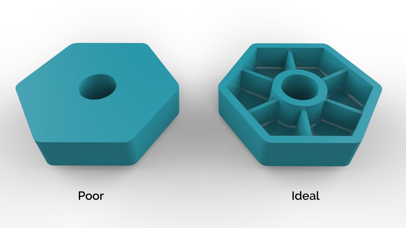
Shell Out Thick Sections
Thick sections can be shelled to help achieve the above guidelines. Ribs can be added to increase part strength. Guidelines for rib design are as follows:
- Ribs should have a maximum thickness of 0.5 times the wall thickness.
- Ribs should have a maximum height of 3 times the wall thickness.
- Ribs should have rounded edges to help avoid sink marks.
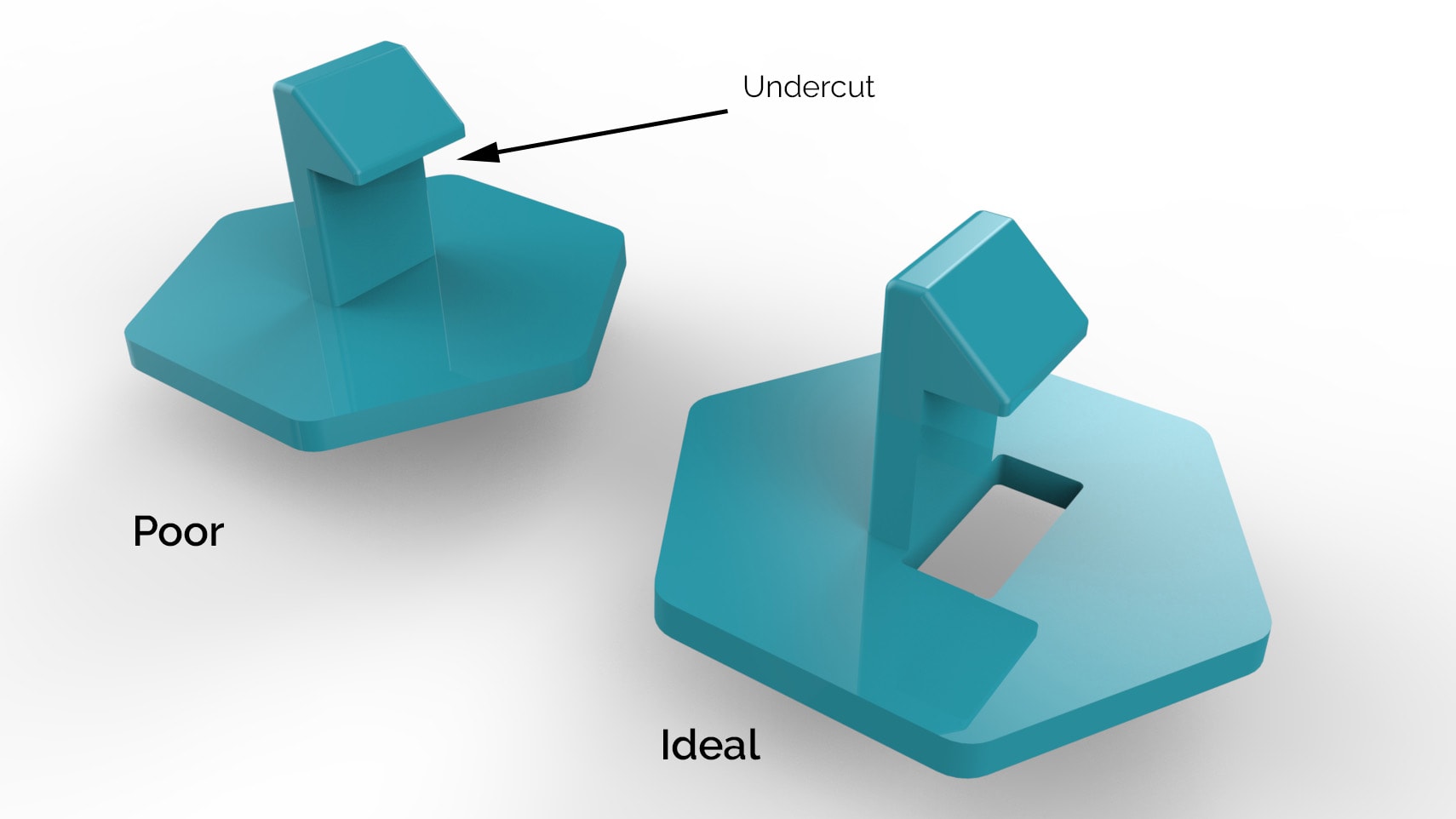
Avoid Undercuts
Undercuts are one of the primary elements you will need to consider as the designer of injection moulded parts. The simplest mould would be a straight-pull mould and consists of two halves. Features with undercuts would prevent the part from exiting the mould and so should be avoided.
If undercuts cannot be avoided, it is sometimes possible to design in features to the mould to allow undercuts, however this will add complexity and cost to the mould. It may also add additional parting lines to the finished part.
Another approach could be an additional sliding core to the mould. This adds complexity and cost, however, is relatively routine and often required. If you opt for this approach, you will also need to consider appropriate draft angles for the core.
Here are a few potential solutions to undercuts:

Round Edges
Sharp edges cause strength concentrations in the part and impede material flow within the mould. For best results round all edges.
- Internal edges should be rounded to a minimum of 0.5 times the wall thickness.
- External edges should be rounded to a minimum of 1.5 times the wall thickness.

Adding Text or Logos
Text and Logos are a common feature to include in injection moulding. It is easier to have embossed text (raised) rather than recessed, because it is easier to machine, however either option if possible. For best results:
- Emboss text by 0.5mm.
- A minimum font height of 5mm is best.
Thread Features
There are two main ways to add a thread into an injection moulded part. Each method has its merits and is suited to different applications.
Moulded Thread
A moulded thread is a thread moulded directly into the tool (an example of this is a bottle lid). Because the thread creates undercuts, then in order to remove the part from the tool, the thread will need to be unscrewed. For this reason, the tool will need to be more complex and costly.
Generally, this will be best suited to larger threads on a simpler overall part.
Bosses
Bosses are very common method of creating an attachment point in injection moulding. They are simply cylindrical extrusions that can accommodate a self-tapping screw, metal threaded insert or feature from another part.
Metal threaded inserts can be added into the boss by ultrasonic, thermal or in-mould insertion. These allow machine threads and are well suited to higher load applications or which require many cycles of assembly and disassembly.
Best design practice for bosses are as follows:
- Outside diameter 2 times the internal diameter.
- Add chamfer to guide screw or insert into hole.
- The hole should extend to the wall level.

Snap-fit Joints
Snap-fit joints are a common and cost-effective method of joining two parts without fasteners. They can be tricky to design to provide the correct assembly force and retention, so best to consult with the manufacturer unless you have a lot of experience with this.
Remember to apply all previous rules of wall thicknesses and undercuts, although it is possible to include an undercut for snap-fits, it does require additional tool complexity.
Try to keep the snap-fit thickness a minimum of 0.5 times the wall thickness.
Living Hinges
Living hinges are thin pieces of plastic that join two segments to allow it to bend and flex (lid of a plastic ketchup bottle). If designed well, they can last for many tens of thousands of cycles before failure. However, it can be difficult to design a reliable living hinge and best to ask your manufacturer for advice if you are not experienced.
There are many sources on the web for how to design a living hinge for injection moulding, but some basic rules of thumb include:
- Recommended wall thickness of 0.25-0.35mm
- Flexible materials such as Polypropylene (PP), Polyethylene (PE) and Nylon (PA) are good choices.
- Before going to production, best to prototype the living hinge on a CNC machine.
- Hinges longer than 150mm should be divided to improve lifespan.

Surface Finish
Surface finishes can significantly affect the look of the finished part. They can also affect the mechanical properties of the part as friction will increase as average surface finish (Ra) increases. This friction will also lead to increased wear on the tool and so more generous draft angles maybe required.
| Finish | SPI* Standard | Finishing Method | Typical Surface Roughness Ra (μm) |
|---|---|---|---|
| Super High Glossy | A-1 | Grade #3, 6000 Grit Diamond Buff | 0.012 – 0.025 |
| High Gloss | A-2 | Grade #6, 3000 Grit Diamond Buff | 0.025 – 0.05 |
| Normal Glossy | A-3 | Grade #15, 1200 Grit Diamond Buff | 0.05 – 0.10 |
| Fine Semi-Glossy | B-1 | 600 Grit Paper | 0.05 – 0.10 |
| Medium Semi-Glossy | B-2 | 400 Grit Paper | 0.10 – 0.15 |
| Normal Semi-Glossy | B-3 | 320 Grit Paper | 0.28 – 0.32 |
| Fine Matte | C-1 | 600 Grit Stone | 0.35 – 0.40 |
| Medium Matte | C-2 | 400 Grit Stone | 0.45 – 0.55 |
| Normal Matt | C-3 | 320 Grit Stone | 0.63 – 0.70 |
| Satin Textured | D-1 | Dry Blast Glass Bead #11 | 0.80 – 1.00 |
| Dull Textured | D-2 | Dry Blast #240 Oxide | 1.00 – 2.80 |
| Rough Textured | D-3 | Dry Blast #24 Oxide | 3.20 – 18.0 |
| As Machined | – | Finished to the Machinist’s Discretion | 3.20 (with visible machining marks) |